Rapid Data for Rapid Transit
When California’s Bay Area Rapid Transit (BART) first opened to passenger traffic in 1972, it was the first new rail rapid transit system built in the U.S. in over 60 years. Traversing complex geography and varied population densities, BART used ionnovative technologies and construction methods to provide the region with high-speed commuter rail service. As it approaches its 45th anniversary, BART has expanded along both sides of the San Francisco Bay. Today the system includes 167 km (104 mi) of track and carries roughly 122 million passengers each year. It’s still growing.
The Warm Springs extension adds a new station and over 5 miles of new track to the BART system.
In 2009, BART began work to extend service along the southeast side of the bay, adding 8.7 km (5.4 mi) of railway and a new station to bring service to the Warm Springs district in the city of Fermont. Expected to open for passenger service in late 2016, the $890 million project features both subway and surface track, including a tunnel beneath Fremenont’s Lake Elizabeth and several vehicular overpasses.
In order to ensure sage operations, BART required its construction contractor, Kiewit Corporation, to conduct precise measurements to verify that the more than 18 km (11 mi) of new track cloasely matched the design alignment. The track which is rated to speeds of 180 kph (110 mph), could not vary from design by more than 1.3 cm (0.5 inch). Although Kiewit was capable of handling much of the work, the contract called for verification of the rails by an independent surveyor.
Kiewit managers contacted Jim Dickey, President of Cinquini & Passarino, Inc. (C&P), a Northern California-based surveying firm with expertise in railway surveying. The two companies had worked together previously and Kiewit was confident with the technologies and processes that C&P would use on the BART extension.
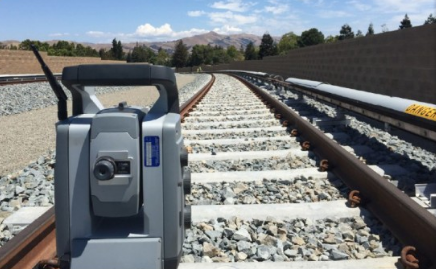
Mounted on its own trolley, a Trimble S8 measures to the prism trolley team visible. The robotic instrument automatically tracked the target and transmitted data to the prism trolley.
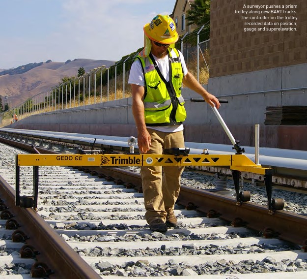
C&P planned to measure the railwas using a pair of Trimble GEDO trolleys. The trolleys are placed on the tracks; each trolley can be pushed and operated by one person. The instrument trolley carries a Trimble S8 1” total station. The prism trolley carries a small retroreflector for the total station together with a tilt sensor to measure transverse inclination and a gauge sensor to measure distance between the rails. Radio data links connect the total station to a Trimble TSC3 controller on the prism trolley, enabling the instrument to operate unattended during measurements. The controller uses GEDO Vorsys software to manage the sensors and record the data.
One of the key aspects of the survey-control was quickly addressed. “Kiewit provided points about every 500 feet along the project corridor”, Dickey recalled. “They had used good procedures for the horizontal conponent and they had done digital leveling for all the vertical components, so the control fit very will.”
To measure the track, a C&P surveyor placed the instrument trolley on the track adjacent to a control point. The operator then oriented the total station to the trolley and measured to the control point before pusing the instrument trolley ahead to the next control point, roughly 150 m (500 ft) along the track. Then the total station measured to that point and back to the prism trolley, which had been placed on the track next to the first control point.
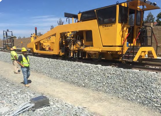
Using information from the trolley measruements, a tamping machine adjusts the rails to match design specifications. Post-tamping measurements confirmed accurate alignment.
With the instrument oriented to the track and control, an operator could then push the prism trolley along the track, stopping for measurements at 3-ft (1 m) intervals. When the prism trolley reached the total station, a second operator moved the instrument trolley ahead to the next control point and repeated the process. The crew could collect complete data – coordinates and elevation on both rails along with gauge and superlevation – in a single pass.
The trolley enabled C&P to provid a much denser dataset than conventional track surveys. ” We collected points every 1 m (3 ft) along the track,” Dickey said. “When Kiewit was doing track inspection they were measuring the track every 15 to 30 m (50 to 100 feet). We discovered some pleaces in between their checks that needed attention.”

C&P prepares to measure a section of track. In 12 days the team covered more than 11 miles capturing data at 3-ft intervals.
The team needed roughly twelve days to collect as-built data on more than 11 miles (18 km) of track. They mad regular quality checks on each day’s data, waiting to do final processing until all of the track measurements were complete. The deliverables consisted of eletronic data and hardcopy reports, including charts showing the design and measured track alignments in horizontal and vertical axes. C&P used output from GEDO office software and reformatted it to meet the client’s requirements. Kiewit used the information to adjust the track as needed, using either a large track tamping machine or maual methods.
After the initial surveys were complete, C&P performed additional measurement on sections of the track. We’d re-survey 3,000 feet (900m) in a couple of locations,” Dickey said. “We would process that data in Kiewit’s on-site office before we left for the day. We could give them as close real-time results as possible. “C&P also performed post-tamping measurements to confirm that the track adjustment produced the needed results.
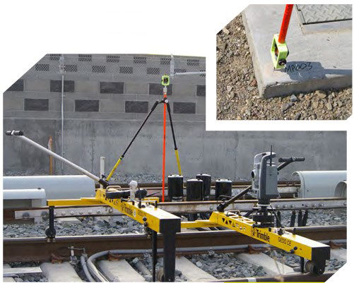
The instrument and prism trolleys set up adjacent to a control point. Control points were located roughly 500 ft apart.
Working on newsly constructed track made the entire process faster and easier. Because train and tes operations had not yet begun, there was no need to coordinate measruements with rail traffic; construction activities were managed to minimize impact on the measurement team. The surveys came in on schedule and within the planned budget.
C&P’s decision to work in railway surveying has paid off. The company has used its capabilities to add new clients and expand to projects across the country. Dickey said the success comes from focusing on their clients’ needs. “Using the GEDO we’re gettin more and better data in less time,” he said. “It’s a big benefit. We’re giving track geometry reports that the clients and owners can undersatnd and use. Everybody needs to keep an open eye for new technologies. Just because you’ve been doing sopmething one way for 20 or 30 years doesn’t mean that there’s nor a better way to take data or measure how track is installed. The amoung of data that we’re able to get out for the track geometry is very impressive.”
This articles was published in the American Surveyor (Vol. 13, No. 11, December/2016)

About the Author

As the market leader in positioning solutions for construction and surveying, Trimble offers a wealth of experience and an extensive product range for tasks in the track environment. The solutions offered range from software for the creation of feasibility studies and route finding to systems for inventory taking and system solutions for machine control and track measurement for construction and maintenance.